
As we are getting close to Halloween, I’ll present this project I did last year. It is about a pair of leds that will light up when there is a loud sound, such as a person raising her voice. The intensity of the leds will depend on the loudness. I used yellow leds as the eyes for a moose/elk antler trophy at my cottage. For this project, as for many others, I used a Picaxe 08M2 microcontroller. Picaxes are inexpensive, very simple to use, BASIC language programmable and Microchip Pic based, see picaxe.com. You can do surprisingly much with them.
The project has two parts, a small board for the Picaxe and another for a sound sensor with condenser microphone, amplifier and peak detector. These are connected by a standard stereo lead with 3.5 mm plugs. The sound sensor was originally for another project, a camera trigger.
The Picaxe part
 The schematic is simple. The Picaxe is powered by 4.5 V from three AA cells. In the left there are the minimum components for software download as described in the Picaxe getting started manual. The leds are driven from picaxe pwm output pin. In the right there are the two leds connected in series and with a 220 ohm resistor. In retrospect, that 220 ohms seems to be somewhat high value. With the yellow leds that I used (their forward voltage being 1.98 V) the maximum current will be only 2.5 mA [ =(4.5V-2*1.98V)/220 ohm ]. They will be dim even at their brightest and therefore only suitable for lowly lit areas like the candlelit room that I used them in. You can lower the resistor value to make them brighter, anywhere down to 33 ohms (that would produce a maximum current of 16mA). Brightness depends on the leds as well, so you may want to experiment. This circuit is not suitable for white or blue leds as the 4.5 volt supply is not enough to light two of those in series (just one would be fine). The forward voltage of white and blue leds tends to be over 3 V so for having two of those in series would require over 6V supply voltage and that is too much for a Picaxe. Red, green and yellow 3 or 5 mm leds should be fine.

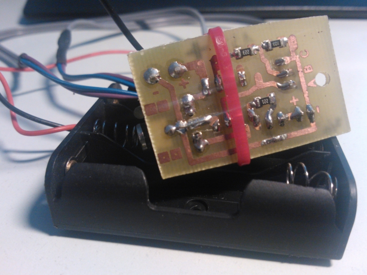
The board has a terminal block for leads from the battery holder. Connection to microphone is via a 3.5 mm stereo socket. The tip supplies to 4.5V to the mic, center has the audio signal and base connects to ground. Led connectors are just header pins. The programming interface is not the standard one as suggested by Picaxe. Picaxe programming cable has a 3.5 mm stereo plug as the connector. The norm is to install a 3.5 mm stereo socket that connects to pins corresponding to mine here. I found it to be a pain to install these 3.5 mm sockets to each board that I made, so I created a simple adapter (image below) from a stereo socket to a 3-pin female header. This way I only need to have these 3 pins on the boards. The letters CBA correspond to the download circuit description in the Picaxe manual and help me to get the connector orientation right when programming.


The sound sensor
 The sound sensor uses an inexpensive electret condenser microphone. It is powered via a 2.2k resistor R1 (manufacturer guidance). The DC power is blocked by C2, and C2 and R2 form a high-pass filter that filters out sound frequencies below 16 Hz. An op-amp is used to amplify the signal. The amplification is set to 181 times by resistors R3 and R4. In the elementary peak detection part the amplified output is rectified by diode D1, leaving only the positive half of the wave. A schottky diode should be used as they have a lower voltage drop, increasing the remaining voltage for the peak detection. This peak positive voltage gets stored in capacitor C3 for a short while so that the picaxe can read the value. Resistor R5 allows the capacitor to discharge at such slower rate that picaxe can catch the peak.

 The board has the microphone at far left. Condenser microphones are polarised, and in this case the positive leg is on top. The blue circle to the right of the mic is a hole for a screw where I installed a small but strong neodymium magnet. It is handy for attaching the microphone to ferrous metal objects such as nails. I covered the finished board with heat shrink tube as seen below.

Software
The source code file is attached here pwmledv2.
Parts list
| Part | Origin | Cost in eur |
| Picaxe 08M2 | picaxe.com | 2.58 |
| TS272CN operative amplifier | eBay | 0.83 |
| Condenser microphone OBO-04FP-0B | eBay | 0.39 |
| 3 pcs SMD resistors, 1206 | eBay | 0.01 |
| 470uF electrolytic capacitor | eBay | 0.04 |
| 1uF electrolytic capacitor | eBay | 0.04 |
| 0.1uF polyester capacitor | eBay | 0.14 |
| 5 pcs 0.25w resistors | eBay | 0.03 |
| SD101C schottky diode | eBay | 0.06 |
| pin headers | eBay | 0.08 |
| 2 pcs 3.5mm stereo sockets | eBay | 0.18 |
| stereo cable with 3.5mm plugs | ||
| 2 pcs 3mm leds | eBay | 0.06 |
| a half of a 100×160 mm photosensitive PCB | www.tme.eu | 1.40 |
| 2 pin terminal block | eBay | 0.06 |
| 3xAA battery holder | ||
| Total: | 5.70 |