One of the major hurdles when making printed circuit boards at home is to solve how to transfer the PCB design to a copper clad board so that the extra copper can then be etched away. You can print transparencies with your printer and you can get inexpensive photosensitive boards but you still need some source of ultraviolet light for transferring the design to the board. I found some inexpensive 5mm UV leds on eBay and decided to give this a try. Other people had reported success so I was confident that this would work. Of course this is a chicken-or-the-egg type of problem. You need to be able to expose one PCB in order to make a device that you can use to expose PCB’s. Luckily I had access to the tools required. You could also easily construct this on veroboard.
I had an old A4/letter size scanner that was no longer producing sharp scans. The top part with the bed and lid looked just perfect for the exposure box. I wanted to make full use of the available glass area that was about 20 x 30 cm. I ordered 100 pieces of 5 mm UV leds for 4.50 euros. According to the seller they have a peak wavelength of 395 to 405 nm. This is well in line with for example the Positiv-20 photo resist spray that has its sensitivity between 340 and 420 nm. The forward voltage of the leds is specified as 3.2 to 3.8 V, and my measurements confirmed that to be 3.35V at 20mA. Maximum allowed continuous current is 20mA. Viewing angle is 20 to 25 degrees.
If I lay out the leds to a 9 x 11 matrix then it takes conveniently 99 leds. The distances between leds would need to be 2.2 cm and 2.6 cm respectively to cover 20×30 cm. Assuming that the viewing angle of a led is 24 degrees, you can calculate that the cone shaped beams of two leds pointing upwards when placed horizontally at a distance of 2.6 cm of each other will overlap at a height of 7.3 cm. That was a nice excercise in geometry. In practice this means that the distance between the PCB and the scanner glass has to be at least 7.3 cm. Otherwise there will be areas that will not be exposed to UV light. The height of the scanner was only a few cm, so I was unable to use that. I therefore needed to build a new bottom part for the exposure unit. I had some spare plywood so I used that. It has occurred to me afterwards that had I used leds with a much wider angle I may have managed using the scanner bottom as well. If had to redo this then I’d probably use smd leds with 120 degree viewing angle.
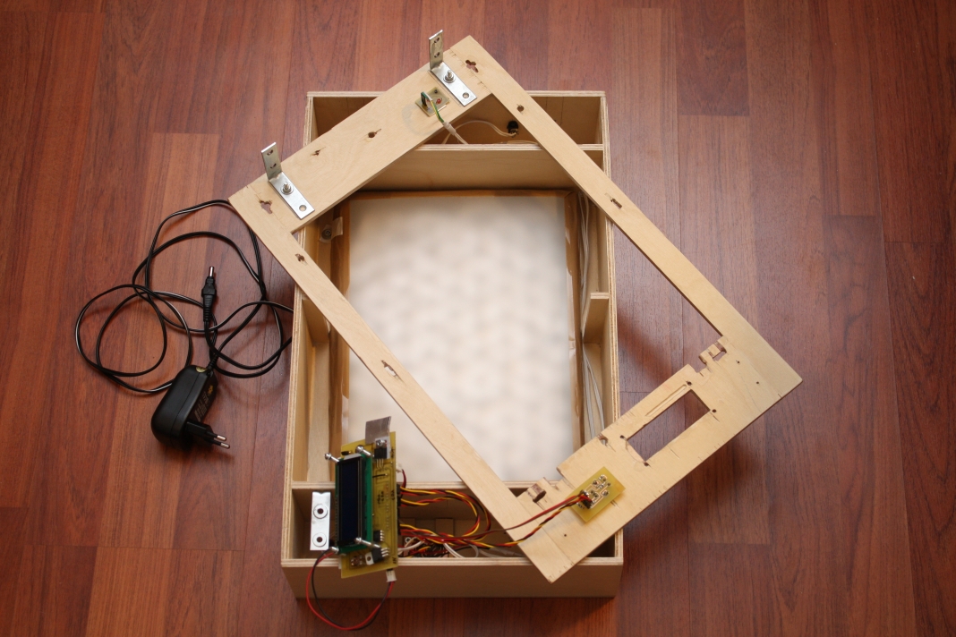
I will not go into details about woodworking as that is not what this blog is about. But I cut the plywood to exact size pieces with a table saw, glued the pieces together, drilled holes, used my dremel tool as well, sanded and finished it with varnish.
I added a power connector to the back of the box. As a power supply I used a generic 1000mA adapter giving out 12V (plus optionally some other voltages as well). In the front you can see a timer unit that I will discuss in a later post. I found out that the light pattern from the leds was uneven, and so I added a sheet of matte printer transparency to diffuse the light. The sheet sits just a little bit above the leds. It is is taped to a frame that I cut off a cardboard box and reinforced with packaging tape. In the back of the lid part there is a red indicator led that is on whenever the UV leds are on. The scanner had an indicator and a light guide and I wanted to make use of them.
The PCB
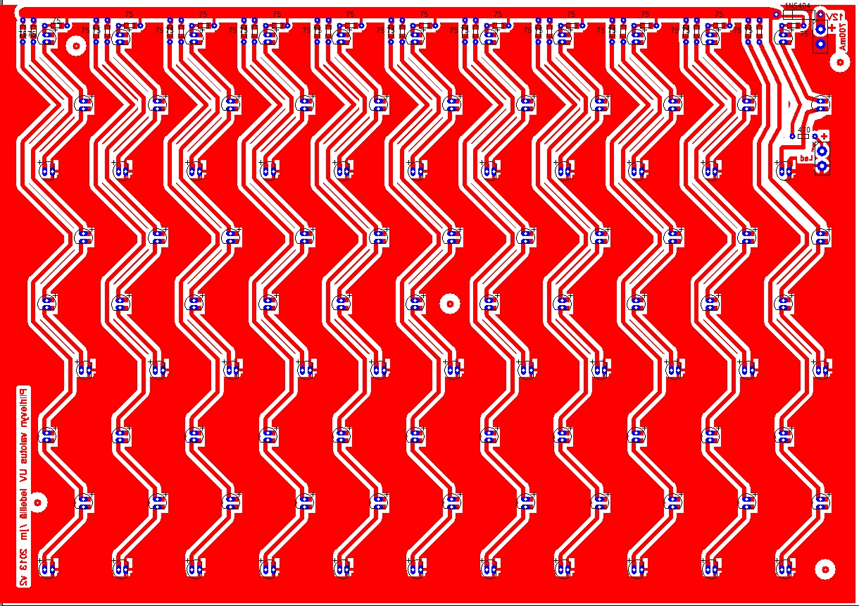
The schematic is simple enough so I did not draw it at all, partly due to the large number of leds. This probably caused an error in design, as I accidentally made my first pcb so that leds were in parallel, not in series as I intended. I still managed to get it to work by adjusting the supply voltage down. This is the corrected pcb below. Click to view it full size.
Power input is at top right. There is also a 3A diode (1N5404) to ensure the correct orientation of the power plug. 1A would have been enough, but I hade these in my drawer. The leds are arranged in series in groups of 3 leds. Each group has a 75 ohm 1206 size SMD resistor in series. These groups are connected in parallel with each other. At the right side there is also a 470 ohm resistor and a terminal block for connection to the red indicator led.
Power supply is 12V. The diode will drop about 0.8V. This leaves 11.2V for each group of three leds and the 75 ohm resistor. The led forward voltage was 3.35 V, so three of them will drop 3*3.35=10.05V. This leaves 11.2-10.05=1.15V for the resistor. With ohm’s law we get that the current through the resistor and each of the leds in that group will be 1.15V/75ohm=0.015A=15mA. And there are 33 of these groups of leds so the total current consumption of the exposure unit will be 33*15mA =495mA. 15mA is less than the allowed maximum for the leds so this could be improved. A 62 ohm resistor would be better, giving 18.5 mA.
The box works well. My exposure times for Positiv-20 sprayed boards are about 12 minutes. Bungard presensitized boards take a little longer, about 14 minutes. This is not a very powerful or fast box, but I’m not in a hurry anyway.
My first pcbs that I created with the box were parts for the Picaxe based timer unit for this box. I will cover that in a later post.
Parts list
| Part | Origin | Cost in eur |
| Scanner bed | scrap | 0 |
| 99 pcs 5 mm UV leds | eBay | 4.50 |
| 33 pcs 75 ohm 1206 resistors | eBay | 0.33 |
| 470 ohm 1206 resistor | eBay | 0.01 |
| 3A diode 1N5404 | eBay | 0.06 |
| red 3mm led | eBay | 0.03 |
| 1000 mA 3-12V power supply | Biltema | 7.99 |
| power connector 5.5mm, 2.1 mm center pin | eBay | 0.15 |
| Total: | 13.07 |


Can i get the layout of pcb led uv exposure box along with circuit schematics thank you
I never created a schematic for this as it was so simple. When you look at the PCB you will see that there are 33 sets that consist three UV leds and a 75 ohm resistor in series. These sets are then connected in parallel with a polarity protecting 1N5404 diode to 12V source. It is not important to have 33 sets, you can vary the number as you like. Additionally there is (a connector for) a red indicator led that is in series with a 470 ohm limiting resistor and in parallel with the 33 sets.
You can see more of the box internals in my article for the exposure timer. The box layout will need to depend on the scanner top that you will be using. The PCB size is 21×29 cm.