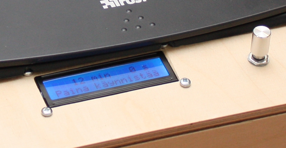
 Quite appropriately, the first board that I exposed with my UV exposure box was a timer to control the exposure. The heart of the timer is a Picaxe 08M2 microcontroller. The timer has also an inexpensive 16×2 characters LCD display (based on a HD44780 controller protocol) and a rotary encoder to set the time. The rotary includes a push button that starts and stops the timer and the exposure. An I2C I/O expander chip PCF8574 interfaces the PICAXE to the display module to save i/o pins on the microcontroller. This way even a small 8-pin microcontroller can be used. The PICAXE uses a power MOSFET transistor to switch power on and off for the UV leds.
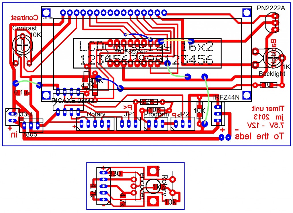
The schematic is below (click to view full size).
At the top there is the power part of the circuit. Power input is the 12 volts for the exposure box. A 78L05 regulator gives a 5V supply for the rest of the circuit. Two capacitors, 0.33uF and 0.1 uF are used to help to stabilize that supply. The IRFZ44N MOSFET acts as a switch for the UV leds. Its gate has a 1K pulldown to ground to keep the switch in off postion unless told otherwise. IRFZ44N has a low resistance when it is on and it helps keeping it cool. A heat sink is still needed. I first tried using an IRF640 MOSFET but it got really hot.
Next there is the PICAXE and its connections. The standard programming interface is at left and those pins are shared with power switch and button functionality. The PCB uses jumpers to disconnect the power switch and the button input when programming. 08M2 has built-in I2C bus support (the SCL and SDA pins) and it is used to communicate with the I/O expander chip that interfaces to the LCD module. The SCL and SDA lines both need to have pull up resistors as per the bus specification. I used 4.7k ohm for those. The values do not need to be exact, and they actually depend on things like the distance between the devices on the bus and the bus speed that is being used. Google “i2c pull up values” for 800000 hits. For my case this 4.7k worked well.
The 8574 I/O expander is being used as sort of extra input and output pins for the picaxe. The picaxe can either set or read the values of the I/O expander’s 8 pins via the serial I2C bus (that consumes only two of the picaxe’s pins) by sending it an 8 bit byte or reading a byte value from it. In this case I’m only sending data to the LCD. An I2C bus can have several devices on it and each device needs to have a specific address associated with it. For 8574 this address is set by pulling a combination of pins 1, 2 and 3 either high or low. Here I have connected those all to ground.
The protocol used by Hitachi HD44780 LCD driver is a de facto standard and you can find plenty of inexpensive LCD modules that are based on it. I got mine on eBay from China for 1.75 euros. It is a two line display with 16 characters per line (16×2 LCD display module). The LCD module actually has a parallel interface with 8 data pins and 3 pins for control purposes (plus pins for power, contrast and led backlight). It can also be configured to use only 4 data pins plus the three control pins. As the 8 bit I/O expander chip has 8 output lines it is adequate for the communication. In simplified terms the communication with the LCD controller happens in two phases so that whenever a byte needs to be sent the high 4 bits are sent first on the data lines and then the low 4 bits after that. The control pins are used to indicate whether it is data or a command that is being sent as well as indicating when the data is ready to be processed.
Whenever picaxe needs to send a byte to the lcd controller there are several bytes that it needs to send to the I/O expander. The control pins need to be toggled and each toggle requires for one byte to be sent. The low and high part of the byte both need one whole byte from picaxe to the I/O expander. That’s shown in the attached code.
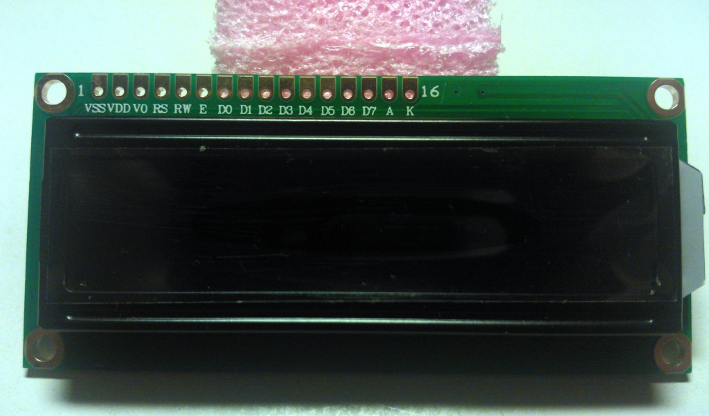
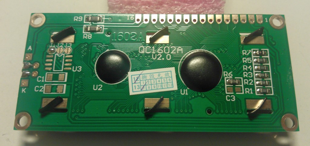
The schematic does not show the pin names for the LCD module, but they are visible in the photos below. The schematic has two trimmer pots, one for lcd contrast and the other for setting the background led brightness. Since there is one “unused” I/O expander output it can be used to switch the background led on or off with the PN2222A transistor. That functionality is not actually being used for anything, it got there just because I copied the design from an earlier project.
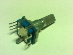
The rotary encoder is a 20 position with push button, 2 bit gray code, 61 euro cent one from eBay. The rotary part has three terminals, one of which is common. The common is connected to positive supply with a 330 ohm resistor. The other terminals are pulled to ground with 4.7k resistors. When turning the knob each position or “click” results in both pins going first up and then down with slightly different timing. The direction that it is being turned to can be detected in software based on which pin goes high first. The push button part of it has a 10k pull down and a 1k limiting resistor as suggested by picaxe manuals for any switch.
The PCB
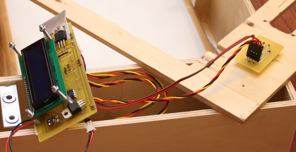
As you can see from the photo of the assembled timer, the pcb is designed so that the LCD piggybacks on the main pcb. The data pins on the LCD align with corresponding pads on the pcb and there are matching holes for screws. A soldered 16-pin sil header (with long pins) connects the pcb to the LCD board.
The rotary encoder is on a separate small pcb to make the placement to the box easier. Getting all the needed holes to align was hard enough already.
The software
The full code is in a zip here pcb_exposure_timer.
The picaxe forums are a great source of information and examples. I used the forums a lot when searching for solutions to various design problems.
At power up the LCD is initialized and a couple of screens of information gets displayed. The picaxe is set to run at 16MHz as writing text to the LCD was a little slow at slower speeds.
The software has two main loops where most of the time is spent. The first one is for waiting for user actions before the exposure has started. The user can either change the exposure time setting or start the exposure. The second loop is the exposure timer when the seconds count down on display. At that point the user can abort the exposure by a button press. The exposure time setting that was used is saved to EEPROM and used as a default the next time.
Turning of the rotary encoder gets detected in a hardware interrupt subroutine. It increments or decrements a global counter value that then gets detected and processed in the first main loop.
The program makes use of some layers of subroutines. I have tried to make the routine names as descriptive as possible to help in understanding how the code works.
Parts list
| Part | Origin | Cost in eur |
| picaxe 08M2 | picaxe.com | 1.80 |
| LCD module | eBay | 1.75 |
| PCF8574 I/O expander | eBay | 0.47 |
| IRFZ44N mosfet | eBay | 0.61 |
| 78L05 regulator | eBay | 0.20 |
| PN2222A transistor | eBay | 0.09 |
| Capacitors, 0.1uF and 0.33uF | eBay | 0.05 |
| Resistors | eBay | 0.10 |
| trimmer pots, 1k and 10k | eBay | 0.36 |
| rotary encoder | eBay | 0.61 |
| Total: | 6.04 |


i have built your timer all works except the button on the encoder which when pressed moves the time down by 10 seconds, every now and then it will start the timer and turn on the leds.
any help would be nice thank you
HI Albert, this sounds to me like the button press will sometimes generate a counterclockwise rotation step, and sometimes it will generate the button press as it should.
Those two signals should not be connected in any way as they go to separate pins of the Picaxe. My first thoughts are either a faulty rotary encoder, or maybe some solder connections between tracks or some etching residue on the pcb. Please check those first.
i am new to this and often the simple things are the ones you miss
Thank you very much i found a hair breath of copper trace between pins 2 and 3 needed high magnification glass to see,once removed works fine now thank you very much for your help, problem solved
It’s great that you got your problem solved .
I have found that a loupe is an irreplaceable aid when examining copper residue on pcb’s. I have one always at hand. The very cheap 10x magnification loupes that sell for 1.30 euros on ebay (including shipping) are perfect for the job. Like this one http://www.ebay.com/itm/131281565426 . Just make sure that you get one that has a diameter of 50 mm and not a tiny 30mm one.
Will check it out again thanks for the help
Thanks just ordered one
Hi Jari. I am interested in building your PCB Exposure Timer with Picaxe and LCD Display.
Everything O.K. till I try and download your code into a Picaxe 08m2+. I am not bad at building circuits but rubbish at programming Picaxes. When I try running your code I get:- bintoascii bTemp, bTemp2, PTRINV#CVAL, PRTINCVAL
Syntax error on lines 129 & 135 corrected by adding _ before 08m2 & 28×2.
Next attempt gives:-
bintoascii bTemp, bTemp2, PTRINCVAL,PTRINCVAL
^
Syntax Error on Line 492 at/before Position 48
Error: @bptrinc cannot be used as a variable.
Any ideas? I this the fully working version of the code? or is there another version of the fully working code.
I would like to say I can fix this but my brain stopped working long before this point in your program. Many thanks in advance Barry Harvey G8RIW g8riw@post.com
Hi Barry,
This is the working code that I have used. It’s just several years old now so I suspect that there could be some minor revisions to the variables from picaxe.
On line 492 the PTRINCVAL’s are actually symbols that are defined on line 132. It could be that the use of the @bptrinc that the symbol points to is not supported in a bintoascii call any more. I’d suggest to try to break the line 492 to separate statements to see if that would help. Unfortunately I no longer have a working environment for this so I can’t test myself.
So something along these lines.
‘ Need to reuse variables fro lcd routines
bintoascii bTemp, bTemp2, bLcdTemp, bLcdByte
@bptrinc = bLcdTemp
@bptrinc = bLcdByte
Then if that works you’d need to do a similar change on line 502.
If this does not solve the issue then I’d suggest that you post a question on picaxe forums. This code is seven years old so there may have been minor changes in the environment since then. The forum is the best place to get answers from the experts.